


Quick Answer
0-10V dimming is an analog low-voltage control method where a 0–10V DC signal adjusts LED driver output from 0% (off or minimum) to 100% (full brightness). It requires two extra low-voltage wires (violet/gray, typically 18 AWG) between the dimmer and each LED driver. Runs up to about 200 ft work with 18 AWG; longer runs may need 16 AWG. 0-10V dimming saves 30–60% on energy costs compared to non-dimmed lighting.
0-10V dimming is the most widely used low-voltage dimming protocol in commercial and industrial LED lighting. It uses a simple analog signal — ranging from 0 volts to 10 volts — to tell an LED driver how bright to operate. At 10V the fixture runs at full power; at 1V it dims to roughly 10%. Two thin, low-voltage wires are all that separate a standard LED installation from a fully dimmable one.
Use 0-10V dimming when the fixture, driver, and control plan all support low-voltage dimming. For LED high bay lights, that usually means zoning aisles or work areas. For LED parking lot lights, it often means pairing dimming leads with photocells, schedules, or motion sensors. For LED troffers, it means confirming the wall control is rated for 0-10V and that the low-voltage violet/gray leads are carried through each fixture in the zone.
Watch: 0-10V Dimming Explained in 6 Minutes
How 0-10V Dimming Works
Key takeaway: 0-10V dimming uses two dedicated low-voltage DC wires — completely separate from the AC power supply — to send an analog signal from a dimmer switch to the LED driver. The voltage level (0–10V) tells the driver what percentage of maximum brightness to output. The dimming signal does not restrict line power; flicker performance and transformer needs depend on the driver and fixture design.
Traditional dimmers used for incandescent bulbs work by restricting (chopping) the AC power waveform. This approach causes problems with LED drivers: flickering, buzzing, reduced lifespan, and a hard limit of roughly 150 watts per circuit. LEDs convert AC to DC internally and need a clean, constant power supply to operate correctly.
0-10V dimming solves this by keeping the AC power supply untouched and using a separate low-voltage signal circuit to communicate the desired brightness level. Here is how the signal maps to output:
- 10V signal → 100% brightness (full output)
- 7.5V signal → ~75% brightness
- 5V signal → ~50% brightness
- 2.5V signal → ~25% brightness
- 1V signal → ~10% brightness (minimum on most modern drivers)
- 0V signal → 0% or ~10% depending on driver type (0-10V vs. 1-10V)
The dimmer switch itself is essentially a variable resistor (potentiometer) that sinks current from the driver's internal 10V reference. When the dimmer is set to maximum, it presents high impedance and the driver sees a full 10V — 100% output. As the dimmer knob or slider is turned down, it sinks more current, dropping the voltage and proportionally reducing light output. This analog approach is simple, reliable, and requires only two thin wires regardless of how many watts the fixture draws.
0-10V Wiring Diagram
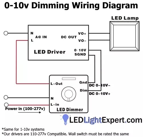
Key takeaway: A 0-10V wiring diagram shows two separate wire sets: the standard AC power wires (hot, neutral, ground — typically 12–14 AWG) and two additional low-voltage DC signal wires (positive + and negative −, typically 18 AWG shielded). The AC wires power the fixture; the signal wires control brightness.
The diagram below shows a standard 0-10V dimming installation. The AC power (120V or 277V) feeds through the dimmer's line-voltage switch to the fixture driver. The two low-voltage 0-10V signal wires connect the dimmer's dimming terminals to the driver's dimming input leads — usually color-coded purple (+) and gray (−).
Wire Color Codes
- Purple (violet) — 0-10V positive (+) dimming signal
- Gray — 0-10V negative (−) dimming signal / common
- Black — AC hot (line voltage)
- White — AC neutral
- Green or bare copper — Ground
For the 0-10V signal wires, 18 AWG shielded 2-conductor cable is recommended for runs up to 200 feet. The shielding reduces electromagnetic interference from adjacent AC power conductors. Most US jurisdictions classify the 0-10V wires as Class 2 low-voltage and do not require conduit, but always verify with your local authority having jurisdiction (AHJ). The AC power wires (12–14 AWG) must use an NEC-approved wiring method for the location.
0-10V vs. 1-10V Dimming
These two terms cause frequent confusion, but the distinction is straightforward: it comes down to minimum dim level and how the lights turn off.
Early 0-10V systems used true 0-volt dimming — the fixture would dim all the way to off (0% output) when the signal hit 0V. Modern LED drivers have shifted to 1-10V for two practical reasons:
- Safety: Having live AC power feeding a fixture that appears to be off (0V signal, no light) creates a hazard — someone might assume the circuit is de-energized when it is not.
- Driver longevity: Holding an LED driver at constant power with zero output stresses internal components. Moving the off function to a dedicated switch (designed to handle repeated on/off cycling) extends driver lifespan.
From an installation perspective, 0-10V and 1-10V use identical wiring, identical switches, and identical signal wires. The only behavioral difference is that a 1-10V fixture will hover at approximately 10% output when the dimmer is turned to minimum — you need the line-voltage on/off switch (built into powered dimmers like the Lutron DVSTV) to fully cut power. Do not assume any LED fixture will dim to off; check the driver spec sheet for the minimum dim level.
Types of 0-10V Dimmer Switches
There are two main categories of 0-10V dimmer switches: powered and unpowered (signal-only). Choosing the right type depends on your wiring setup and whether you need integrated on/off control.
Powered Dimmer (Recommended)
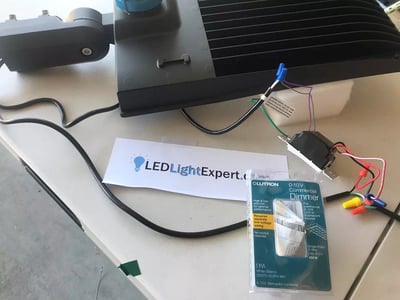
Includes both line-voltage on/off switch and 0-10V dimming control in one wall unit. Connects to AC hot, neutral, ground, and the two 0-10V signal wires. Example: Lutron DVSTV-WH ($40–70). Works with 0-10V and 1-10V drivers. Most common choice for new installations.
Unpowered Dimmer (Signal-Only)
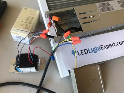
Connects only to the two 0-10V low-voltage signal wires — no line-voltage connection. Adjusts the dimming level but cannot turn the lights on or off. Requires a separate line-voltage switch or relay for power control. Example: Lutron DVTV. Less common; used where a separate power switch already exists.
For most commercial LED installations — especially high bay lights and parking lot lights — a powered dimmer is the recommended choice. It simplifies wiring, reduces the number of wall devices, and ensures clean on/off control alongside smooth dimming.
0-10V Dimming vs. Other Dimming Protocols
0-10V is not the only way to dim LED fixtures. Here is how it compares to the three other common protocols:
| Feature | 0-10V | DALI | Triac / Phase-Cut | PWM |
|---|---|---|---|---|
| Signal Type | Analog DC voltage | Digital bidirectional | AC waveform chopping | Digital pulse train |
| Wiring | 2 low-voltage + AC power | 2 low-voltage + AC power | AC power only (in-line) | 2 low-voltage + AC power |
| Max Fixtures / Circuit | 50+ (amp-limited) | 64 per DALI bus | 1–10 (wattage-limited) | Varies by controller |
| Dimming Range | 10–100% (1-10V) or 0–100% | 0–100% | 10–100% typical | 0–100% |
| Individual Addressing | No (zone only) | Yes (per fixture) | No (zone only) | Possible with controller |
| Feedback / Status | None (one-way) | Yes (two-way) | None | Varies |
| Switch Cost | $40–70 | $200–500+ | $15–40 | $50–150 |
| Installation Complexity | Low | High (commissioning) | Low | Medium |
| Common Fit | Commercial / industrial zones | Large buildings / BMS | Residential (low wattage) | Architectural / entertainment |
| Max Wattage / Switch | 2,200W+ (at 277V) | Varies by controller | ~150W (LED) | Varies by controller |
For most commercial and industrial LED lighting projects — warehouses, parking structures, offices, retail — 0-10V dimming delivers a strong combination of simplicity, cost, and reliability. DALI is the right choice when individual fixture control and building management integration are requirements. Triac dimmers should be limited to residential and light-duty applications under 150 watts of LED load.
What LED Fixtures Work with 0-10V Dimming?
Any LED fixture with an integrated 0-10V dimmable driver is compatible. Look for "0-10V dimmable" or "dimming 0-10V" on the spec sheet. The most common 0-10V light fixture categories include:
- LED High Bay Lights — UFO and linear fixtures for warehouses, factories, gyms (100–300W+). Most high bay LEDs include 0-10V dimming standard.
- LED Parking Lot & Flood Lights — Shoebox, area, and flood fixtures for outdoor commercial lighting. 0-10V dimming enables after-hours energy savings.
- LED Troffers — 2x2, 2x4, and 1x4 recessed ceiling fixtures for offices and commercial interiors.
- LED Panel Lights — Flat, edge-lit fixtures for drop ceiling grids. Virtually all panels include 0-10V dimming.
- LED Canopy Lights — Gas station, overhang, and parking garage surface-mount fixtures.
- LED Vapor-Tight Lights — Sealed IP65+ fixtures for wet, dusty, and corrosive environments.
- LED Wall Packs — Exterior building-mounted fixtures for perimeter and security lighting.
- LED Corn Bulbs (E39 base, 36W+) — Higher-wattage mogul-base retrofit bulbs with 0-10V-capable internal drivers.
When specifying a 0-10V light fixture, also verify the driver's minimum dim level (typically 10% for 1-10V), maximum wattage selectable range, and whether the dimming wires exit the fixture pre-terminated or require field connection.
Benefits of 0-10V Dimming for LED Lighting
Key takeaway: 0-10V dimming delivers energy savings of 30–60%, extends LED driver lifespan, and provides smooth, flicker-free control — all for roughly $40–70 per zone in hardware cost. It is the simplest and most cost-effective dimming protocol for commercial and industrial LED installations.
- Energy savings up to 60% — Dimming LED fixtures to 50% output reduces energy consumption by approximately 50%. Combined with occupancy sensors, warehouses and parking garages routinely achieve 40–60% lighting energy reductions.
- Extended LED driver lifespan — Running LED drivers below maximum output reduces thermal stress on components. A fixture dimmed to 75% can last 30–40% longer than one running continuously at full power, according to driver manufacturer data.
- Smooth, flicker-free operation — Unlike Triac dimmers that chop the AC waveform, 0-10V delivers a clean DC signal. The result is smooth, continuous dimming from 100% down to 10% (or 0%) with no visible flicker at any level.
- Simple, low-cost installation — Only two additional thin low-voltage wires are needed. No expensive digital controllers, no commissioning software, and no specialized training. A powered 0-10V dimmer switch costs $40–70 — roughly one-fifth the cost of a DALI controller.
- High wattage capacity per switch — A single 0-10V dimmer rated at 8 amps can control 2,200+ watts of LED load on 277V circuits. That is enough for 15+ high bay fixtures per switch — far more capacity than Triac dimmers (roughly 150W of LED load).
- Sensor and automation compatible — 0-10V interfaces directly with occupancy sensors, photocell controllers, and building automation systems (BAS) through standard 0-10V output modules. No protocol conversion needed.
- Zoning flexibility — Multiple dimmer zones can be created independently. Each zone (aisle, bay, perimeter) gets its own dimmer switch or sensor, allowing different brightness levels across a facility without complex programming.
- Industry standard with universal support — 0-10V dimming has been in use for over 40 years and is supported by virtually every commercial LED driver manufacturer. Compatible components are widely available.
How to Install 0-10V Dimming: 8-Step Guide
This step-by-step guide covers wiring a 0-10V dimmer switch to LED fixtures. The process is straightforward for a licensed electrician — the low-voltage control wires are Class 2, and the line-voltage connections follow standard switch wiring practices. Total installation time is approximately 30–45 minutes per zone.
Supplies Needed
- LED fixture(s) with 0-10V dimmable driver
- 0-10V compatible wall dimmer switch (e.g., Lutron DVSTV)
- 18 AWG shielded low-voltage wire (2-conductor)
- Wire nuts sized for 18 AWG
- Electrical tape
Tools Needed
- Wire strippers
- Screwdriver (flathead and Phillips)
- Voltage tester / multimeter
- Ladder or lift (for high bay installations)
Step 1: Verify Fixture Compatibility
Confirm your LED fixture has a 0-10V (or 1-10V) dimmable driver. Check the spec sheet or look for purple and gray dimming wires (marked + and −) coming from the fixture. Not all LED fixtures support 0-10V dimming — verify before purchasing a dimmer switch.
Step 2: Select the Right Dimmer Switch
Choose a 0-10V dimmer rated for your total LED load. A powered dimmer (like the Lutron DVSTV) is recommended — it includes both on/off and dimming in one unit. Verify the switch amp rating covers your total fixture wattage. Most commercial switches handle up to 8 amps.
Step 3: Plan the Wire Routing
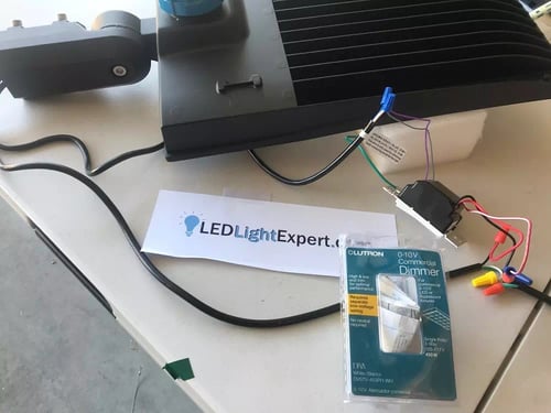
Map the wire path from each fixture to the dimmer switch location. Calculate total wire length and number of fixtures per switch. Keep the total run within the dimmer and driver manufacturer's limits; 200 ft with 18 AWG wire and 300 ft with 16 AWG are common planning limits. For multiple fixtures, plan either a daisy-chain topology (wire from fixture to fixture in series) or a home-run topology (individual wires back to the switch).
Step 4: Turn Off Power at the Breaker
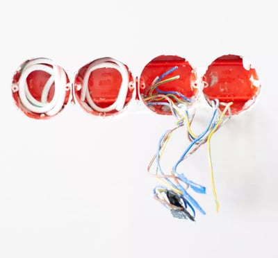
Kill power at the circuit breaker for the lighting circuit. Use a voltage tester to confirm zero voltage at the fixture and switch box. Never work on live circuits. Use proper fall protection and lockout/tagout procedures for high bay installations.
Step 5: Run the Low-Voltage Dimming Wires
Run 18 AWG shielded 2-conductor wire from the dimmer switch location to each fixture. Designate one conductor as positive (+, typically white-striped) and one as negative (−, plain). Low-voltage Class 2 wire does not require conduit in most US jurisdictions per NEC, but should be secured and supported per local code. Keep the signal wire at least 6 inches from high-voltage conductors to minimize electromagnetic interference.

Step 6: Connect Wires at Each Fixture
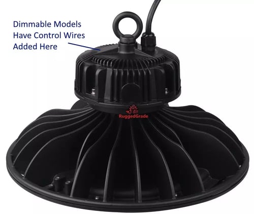
At each fixture, connect the positive (+) dimming wire to the fixture's positive dimming lead (usually purple) and the negative (−) wire to the negative lead (usually gray) using appropriately sized wire nuts. For daisy-chaining multiple fixtures, pigtail the signal wires through each junction box.
Step 7: Wire the Dimmer Switch
At the wall box, connect the 0-10V positive and negative wires to the corresponding terminals on the dimmer. For powered dimmers, also connect the line-voltage hot, neutral, and ground wires per the manufacturer's wiring diagram. Secure the switch to the wall box and install the cover plate.
Step 8: Restore Power and Test
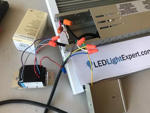
Turn the breaker back on. Verify all fixtures illuminate at full brightness. Slide the dimmer down to confirm smooth dimming without flicker. Test at 100%, 50%, and minimum levels. If any fixture flickers, check wire connections and polarity. Confirm the on/off function works correctly on powered dimmer switches.

Troubleshooting Common 0-10V Dimming Issues
Even with correct wiring, 0-10V dimming installations can encounter problems. Here are the most common issues and their solutions:
Lights Flicker When Dimmed
- Wrong dimmer type — Verify you are using a 0-10V dimmer, not a Triac/phase-cut dimmer. Triac dimmers chop the AC waveform and cause flicker in LED drivers.
- Loose connections — Check all wire nut connections on the 0-10V signal wires. A loose or intermittent connection causes the signal to fluctuate.
- Reversed polarity — Swap the positive and negative control wires at the fixture or switch if the signal wires are connected in reverse.
- Electromagnetic interference — If the 0-10V wires run close to high-voltage conductors without shielding, EMI can cause signal noise. Use shielded cable and maintain 6+ inch separation.
Lights Do Not Dim Below 30–40%
- 1-10V driver limitation — Most commercial LED drivers are 1-10V, which means minimum dim is approximately 10%. Some drivers have a higher minimum threshold. Check the driver spec sheet for minimum dim percentage.
- Voltage drop on long runs — If the control wire run exceeds 200 ft with 18 AWG wire, voltage drop reduces the signal reaching the driver. Step up to 16 AWG or 14 AWG wire.
- Too many fixtures on one switch — Each driver draws a small amount of current (sink current) from the 0-10V signal. Exceeding the dimmer's maximum driver count reduces signal voltage. Split fixtures across two dimmers.
Lights Will Not Turn Off from Dimmer
- 1-10V vs 0-10V — A 1-10V driver will not turn off via the dimming signal alone. It only dims to ~10%. Use a powered dimmer switch (which includes an on/off function) or add a separate switch to cut AC power.
- Driver mismatch — Some older drivers require a minimum hold current that the dimmer cannot reduce to zero. Verify dimmer and driver compatibility.
Different Fixtures Dim to Different Levels
- Mixed driver brands — Different driver manufacturers may interpret the 0-10V signal slightly differently. For uniform dimming across a zone, use the same fixture model and driver brand.
- Unequal wire lengths — Fixtures on longer wire runs receive a lower signal voltage due to line loss. Equalize wire lengths or use home-run wiring topology instead of daisy-chain.
Dimmer Switch Gets Hot
- Overloaded — The total wattage on the dimmer exceeds its amperage rating. Calculate total load: watts ÷ voltage = amps. An 8-amp dimmer on 120V handles 960W maximum. Reduce the fixture count or split across multiple switches.
- Poor ventilation — A dimmer recessed in a tight gang box with other switches may overheat. Use a deeper box or move to a larger enclosure if the switch is warm to the touch.
0-10V Dimming FAQs
0-10V dimming (zero to ten volt) is an analog low-voltage lighting control protocol that uses a DC signal ranging from 0 volts to 10 volts to set LED driver brightness. At 10V the fixture runs at 100% output; at 5V it runs at approximately 50%; at 0V (or 1V in most modern drivers) it dims to minimum or off. Two additional low-voltage wires (typically 18 AWG shielded) connect the dimmer switch to the LED driver. It is one of the earliest and simplest signaling systems for lighting control, standardized under IEC 60929 Annex E.
A 0-10V dimmer switch sends a variable DC voltage (0–10V) through two dedicated low-voltage control wires to the LED driver. The driver reads the voltage level and adjusts its output current proportionally: 10V = full brightness, 5V = ~50%, 1V = ~10%. The dimmer acts as a variable resistor (potentiometer) that sinks current from the driver's control circuit. The main AC power wires remain separate and constant — only the signal wires carry the dimming command.
The hardware and wiring are identical. The difference is the minimum dim level: true 0-10V drivers dim all the way to off (0% at 0 volts), while 1-10V drivers only dim to approximately 10% (at 1 volt) and require a separate on/off switch to cut power completely. Most modern commercial LED drivers are 1-10V for two reasons: safety (live wires with no light output is a hazard) and driver longevity (holding constant power at 0% output can shorten driver lifespan). From an installation and switch standpoint, 0-10V and 1-10V systems use the same wiring and dimmer switches.
The 0-10V control signal uses very low current, so thin wire is sufficient. Minimum is 22 AWG, but 18 AWG shielded wire is recommended for runs up to 200 feet (61 m). For longer runs, step up to 16 AWG to minimize voltage drop. The control wires are separate from the AC power wires (which are typically 12–14 AWG). Shielded wire reduces electromagnetic interference from nearby power conductors.
With 18 AWG shielded wire, typical maximum run length is approximately 200 feet (61 m) before voltage drop affects dimming accuracy. Using 16 AWG extends this to roughly 300 feet (91 m). For very long runs in large warehouses or outdoor parking lot installations, 14 AWG shielded control wire can reach 500+ feet. Always verify with the dimmer switch manufacturer's specifications, as maximum wire run varies by model and number of connected fixtures.
Dimming LED fixtures to 50% brightness reduces energy consumption by approximately 50%, since LED power draw is roughly proportional to light output. A facility running 0-10V dimming at 70% average output across all fixtures saves approximately 30% on lighting energy costs. Combined with occupancy sensors on the 0-10V signal, savings of 40–60% are common in warehouses, parking garages, and large commercial spaces. The U.S. Department of Energy reports that dimming controls are one of the most cost-effective energy reduction strategies for commercial lighting.
0-10V is an analog one-way protocol (dimmer sends signal, driver receives, no feedback). DALI (Digital Addressable Lighting Interface) is a digital two-way protocol that allows individual fixture addressing, status feedback, and integration with building management systems. 0-10V is simpler, cheaper ($40–70 per switch), and easier to install. DALI is more capable but costs significantly more ($200+ per controller) and requires specialized commissioning. For zone-level dimming in warehouses, parking lots, and standard commercial spaces, 0-10V is the most cost-effective solution. DALI is preferred for large multi-zone buildings requiring centralized control.
Yes. 0-10V-compatible occupancy and vacancy sensors are available that output a 0-10V signal directly. When motion is detected, the sensor sends 10V (full brightness); after a configurable timeout with no motion, it sends 0V or 1V (minimum/off). Some sensors support stepped dimming — for example, dropping to 30% after 5 minutes of no motion, then off after 15 minutes. High bay occupancy sensors rated for 20–45 ft mounting heights are specifically designed for warehouse and industrial 0-10V dimming applications.
Yes. Many building automation systems (BAS) and lighting control panels include 0-10V output modules that can control 0-10V fixtures as zones. Protocols like BACnet and Zigbee can interface with 0-10V drivers through gateway controllers. This makes 0-10V an effective bridge between simple analog dimming and full building automation without replacing existing fixtures. For new construction requiring individual fixture addressability, DALI or networked LED drivers may be more appropriate, but 0-10V remains the most common analog dimming interface in commercial buildings.
0-10V dimming can also be achieved through resistor dimming or pulse width modulation (PWM). Adding a 50K ohm resistor on a single-driver LED fixture would bring the output to approximately 50%. A 70K ohm resistor would bring it to roughly 70%. This method requires accurate resistors housed in a well-constructed enclosure. The drawback is that it eliminates the ability to dynamically adjust the light level — changing brightness requires physically swapping the resistor. Resistor dimming is for experts only; for most applications, a standard $40–70 0-10V wall dimmer switch is the recommended approach.

To set up a 0-10V dimming system you need: a compatible 0-10V wall dimmer switch (look for 0-10 volt or 1-10 volt dimmer switches — powered versions with on/off control run about $40–70), low-voltage wiring (14–18 gauge shielded wire for the signal lines, plus standard 12–14 gauge for any power lines required by the switch), and a lighting plan. Think through where you want the switches, what zones you want to control independently, and whether you may add Zigbee, DALI, or motion-sensor controls in the future — run the wires to accommodate expansion. The Class 1 wiring (line voltage) turns the device on and off, while the Class 2 wiring (low voltage) provides the dimming control signal between 0V and 10V.
Related Articles
 LED Lighting: A Complete Buying Guide
Everything you need to know about LED lighting — benefits, types, comparisons to traditional technologies, and what to look for when buying.
LED Lighting: A Complete Buying Guide
Everything you need to know about LED lighting — benefits, types, comparisons to traditional technologies, and what to look for when buying.
 Industrial Lighting: A Complete Buying Guide
Complete guide to industrial lighting — high bays, hazardous location lights, retrofit vs. replacement, and a 10-step buying checklist.
Industrial Lighting: A Complete Buying Guide
Complete guide to industrial lighting — high bays, hazardous location lights, retrofit vs. replacement, and a 10-step buying checklist.
 Outdoor Lighting: A Complete Buying Guide
Everything you need to know about outdoor LED lighting — parking lot lights, flood lights, wall packs, and how to choose the right fixtures.
Outdoor Lighting: A Complete Buying Guide
Everything you need to know about outdoor LED lighting — parking lot lights, flood lights, wall packs, and how to choose the right fixtures.

About the Author


References
Need Help With 0-10V Dimming?
Our lighting specialists can help you select the right 0-10V dimmer switch, plan your wiring layout, and choose compatible LED fixtures for any commercial or industrial project.
SHOP LED DRIVERS


