


NextGen LED Parking Lot Lights — Photocell Bypass — How to Bypass the Dusk to Dawn Sensor
Here is a question we are getting a lot: How do I bypass the photocell on your NextGen series lights? Our 300 watt NextGen LED Parking Lot Lights come with a photocell (often referred to as a dusk-to-dawn sensor) by default. It is the giant blue knob on top of the light. It has an opening on one side to allow light in and recognize when it is time to turn on the lights. The way it works is that the power goes through the photocell, and if the sensor thinks it is dark, it makes the electrical connection and sends power to the LED driver. In order to not use it, you will need to do some re-wiring.
The photocell is often not needed where you have a timer or switch controlling the fixture. In these cases the timer is usually a better choice because you can fine-tune the on/off controls. The photocells will often kick on or off a minute or two apart from one another — which can annoy some users, though most would never notice. An astronomical time clock on a 24-pole parking lot will bring every fixture on at the same second; a parking lot full of dusk-to-dawn sensors will not.
What the Photocell Actually Does Inside the Fixture
On a NextGen 300W, the photocell sits in an ANSI C136.10 three-pin twist-lock receptacle on the top casting. The receptacle carries three blades: line (hot) in, neutral, and switched load out to the driver. When ambient lux at the sensor window drops below the trip threshold (typically 1–3 footcandles, set at the factory), the internal relay closes the line-to-load contacts and current flows to the LED driver. When dawn breaks and ambient rises above the drop-out threshold (typically 3–5 footcandles, with hysteresis to prevent chatter), the relay opens and the driver loses power.
Because the photocell is the switching element for the entire fixture, removing it leaves the line-to-load path open. You have two compliant options to close that path: install a shorting cap (a twist-lock device that hard-wires line-to-load inside the receptacle) or hard-wire the driver to the line feed and cap the receptacle unused. The shorting-cap method is the cleanest and is the one we recommend for most retrofits because it preserves the factory-listed electrical path.
NEMA Receptacle Basics — 3-Pin, 5-Pin, 7-Pin
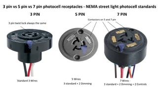
Before you touch anything, confirm which receptacle your fixture uses. The 3-pin vs. 5-pin vs. 7-pin NEMA photocell receptacle guide walks through the physical and electrical differences, but the short version is this:
3-pin (ANSI C136.10). Line in, neutral, switched load out. On/off only — no dimming, no network. This is what the NextGen 300W ships with by default and what a standard twist-lock photocell or shorting cap fits.
5-pin (ANSI C136.41). Adds two 0–10V dimming wires so the receptacle can accept a dimming photocontrol or a wired dimmer from a building automation panel. A simple shorting cap still works to bypass the sensor, but you lose the dimming feed unless you install a dimming bypass cap.
7-pin (ANSI C136.41). Adds two additional communication pins for smart-city networks (DALI, 2G/4G/LoRa nodes, etc.). Bypass on a 7-pin receptacle is the same shorting-cap concept, but if the networked node is doing more than switching — for example reporting energy, runtime, or fault codes — bypassing it disables those functions.
This Should Be Done by a Licensed Electrician
This should be done by a licensed electrician to not void your warranty. Commercial parking-lot circuits are typically 277V or 480V single-phase (some smaller lots run 120/208V), and the wrong landing at the driver input will kill the driver in the first second it is energized. A licensed electrician also documents the work in a way that preserves AHJ sign-off and keeps your insurance clean.
The cost delta is small. A typical bypass on a pole-mounted NextGen 300W runs 15–20 minutes per fixture once the circuit is locked out; a 12-pole parking lot is a half-day job. The long-run value — no driver replacement at year two because someone landed line on the low-voltage dimming terminals — is worth the hourly rate.
Hard-Wire Bypass — Step-by-Step Instructions
The 8-step procedure below is the internal hard-wire method for a NextGen 300W fixture that does not have a shorting cap installed. If your fixture does have a 3-pin NEMA receptacle, the faster path is simply: pull the photocell, twist in a shorting cap, done. The steps below are for the hard-wire scenario.
At a glance: 1. Open the back plate 2. Locate the red and white wires returning from the photocell 3. Disconnect those wires carefully from the crimps and tape up 4. Connect the black wire coming in from the power to the brown wire going into the LED driver 5. Connect the white wire coming in from the power to the black wire going into the LED driver 6. Check your connections and test the light 7. Cover up the photocell ports or just leave the photocell installed 8. Add a sticker with notation inside for future notice. Each step is detailed below.
Warning: Lock out and tag out the circuit at the panel before starting. Verify dead with a non-contact voltage tester AND a meter at the fixture terminals. OSHA 1910.147 lockout/tagout rules and NFPA 70E safe work practices apply to all commercial pole work.
1. Open the back plate. Remove the gasket-sealed back plate on the fixture housing. On the NextGen 300W, this is a 4- to 6-screw plate on the underside of the casting. Keep the gasket intact — you will reuse it on re-assembly, and an installed gasket is what keeps the IP65/IP66 rating of the fixture.
2. Locate the red and white wires returning from the photocell. Inside the driver compartment you will see the three photocell leads coming down from the receptacle: typically red (load from the photocell), white (neutral), and black (line to the photocell). Trace them to the driver terminals before you cut anything — a label, sharpie mark, or phone photo at this stage will save you at step 4.
3. Disconnect those wires carefully from the crimps and tape up. Cut or unclamp the red and white photocell returns, and cap each free end with a properly rated wire nut or heat-shrink. Do not leave stripped copper floating inside the compartment. If you are not planning to re-use the photocell, you can remove the leads entirely at the receptacle end.
4. Connect the black wire coming in from the power to the brown wire going into the LED driver. This is the line-in landing. On most NextGen 300W fixtures the driver's line-in terminal is marked "L" or "brown"; match your feed hot to that terminal. Use wire nuts rated for the conductor gauge (typically #12 or #14 AWG for pole drops) and torque per NEC 110.14(D) using the manufacturer's listed values (typically 10–14 in-lb for #14–12 AWG lugs).
5. Connect the white wire coming in from the power to the black wire going into the LED driver. This is the neutral landing. Match your feed neutral to the driver's "N" or "black" input. Many installers are thrown by that the driver uses black for neutral where North American line wiring uses white — but the driver follows its own color convention printed on the module label. Land by label, not by intuition.
6. Check your connections and test the light. Before you close the fixture, confirm each wire nut is seated and pull-tested, confirm no copper is exposed, and confirm no stray conductor is resting against the driver heatsink or case. Restore power at the breaker and verify the fixture lights cleanly with no flicker.
7. Cover up the photocell ports or just leave the photocell installed. If you removed the photocell, seal the twist-lock receptacle with a NEMA twist-lock cover or shorting cap (depending on the install). Open receptacles are not code-compliant for outdoor fixtures — water will track the terminals and eventually short the line to the housing.
8. Add a sticker with notation inside for future notice. Inside the driver compartment, place a small adhesive label noting the date, the installer, and "PHOTOCELL BYPASSED — SWITCHED BY [timer / BAS / breaker]". Two years from now, the next electrician on the pole will thank you for the 30 seconds this takes.
This will allow you to use these LED Shoebox Lights or LED Parking Lot Lights with a timer or switch. Hope that helps — leave us some comments and let us know. Hope this article and images help you get these installed the way you want.
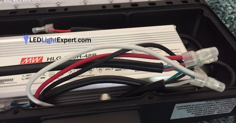
Dusk-to-dawn photocell bypass — fixture open for direct-wire install (photocell control wires identified).
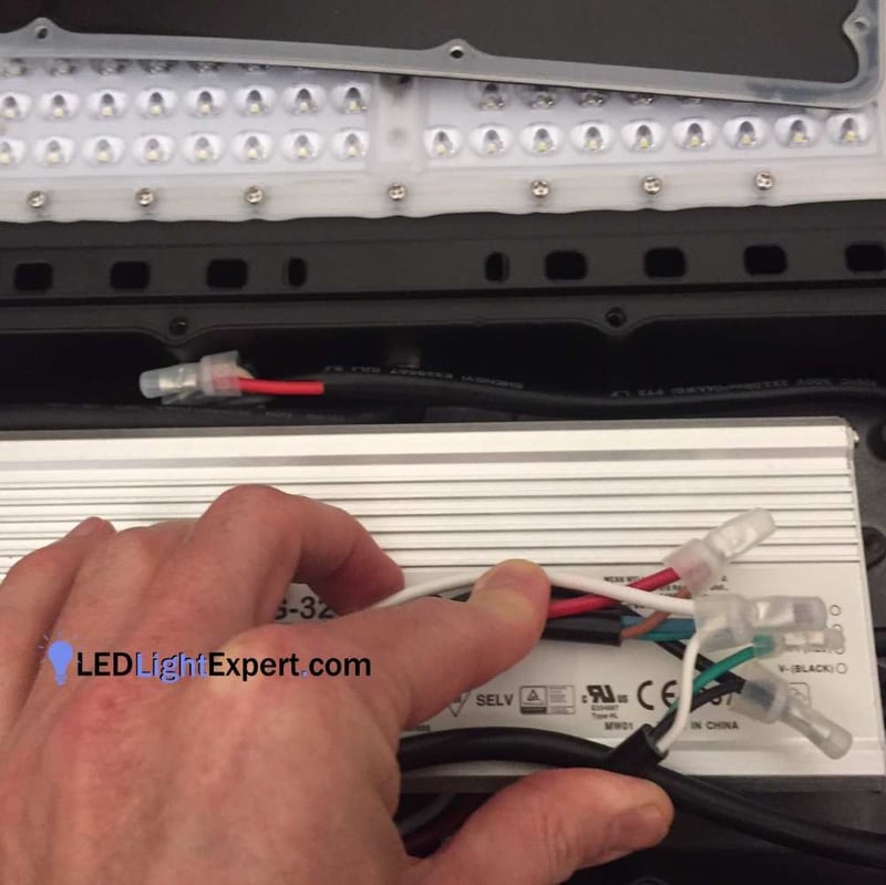
LED Parking Lot Photocell Bypass — driver terminal detail showing line-in (L/brown) and neutral-in (N/black) landing positions.
When to Choose a Shorting Cap, a Timer, or an Astronomical Time Clock
For a single-pole backyard or driveway installation where the client just wants the light on at night, the photocell usually works fine. Leave it in place.
For a small commercial parking lot (4–8 poles) controlled by a wall-mounted contactor or timer, a shorting cap in every fixture is the cleanest solution. Synchronous on/off across the lot, no minute-to-minute drift between sensors, and you get to pick the exact on time to match your business hours.
For a large commercial lot (20+ poles), a municipal installation, or a mixed-use property that wants sunrise/sunset tracking year-round, an astronomical time clock is the preferred control. An ATC computes sunrise and sunset from the site's latitude and longitude and triggers every fixture simultaneously, with programmable offsets (common: 30 minutes before sunset, 30 minutes after sunrise). Pair that with a 0–10V dimming driver on a 5-pin or 7-pin receptacle and you can run a late-night dimming schedule for additional energy savings per IES RP-8 roadway guidance.
For properties planning to migrate to smart lighting controls over the next 3–5 years, specify fixtures with 7-pin receptacles at purchase time even if you are not using the communication pins today — retrofitting a 3-pin casting to a 7-pin receptacle later is expensive and often impractical.
After the Bypass — Code, Warranty, and Commissioning Notes
Three compliance considerations to close out the job. First, modifying the fixture's electrical path technically changes the UL 1598 listing boundary unless you perform the bypass through a UL-listed accessory (a listed shorting cap in the existing receptacle satisfies this; cutting and splicing internal leads does not). For commercial retrofits under AHJ inspection, use the shorting-cap method if possible and keep the cap's UL listing documentation with the project file.
Second, NEC Article 410.130(G) covers luminaire disconnecting means and applies when you rewire a fixture in a commercial setting. On pole-mounted fixtures this is most often satisfied by the in-line fuse holder in the pole hand-hole or by a disconnecting means at the contactor panel; a rewire at the fixture does not change that requirement, but it is worth confirming the disconnect is still functional before sign-off.
Third, document the bypass on the fixture label (date, installer, control method) and in the commissioning sheet. For warranty, most reputable manufacturers — including the NextGen and Aries product lines — warrant the driver for 5 years, and warranty claims move faster when the bypass was done by a licensed electrician and documented on the label. If you ever need to revert to photocell control, unscrew the shorting cap and twist a photocell back in — that is the big advantage of the NEMA receptacle method over hard-wire bypass.
Bypass Decision Checklist
Bypass the photocell only when there is a better control strategy ready to take over, such as a shorting cap plus timer, astronomical time clock, building automation system, or properly commissioned lighting controller. If the photocell failed because of water entry, surge damage, loose wiring, or an incorrect voltage match, fix that root cause before putting the fixture back in service.
| Option | Best use |
|---|---|
| Shorting cap | Use when the fixture should stay powered and another control turns the circuit on and off. |
| New photocell | Use when dusk-to-dawn control is still desired and the receptacle is sound. |
| Astronomical timer | Use for predictable schedules where photocell nuisance switching is a problem. |
Frequently Asked Questions
What does bypassing the photocell on a NextGen parking lot light actually do
Why would I bypass the photocell instead of leaving it in
What is a NEMA photocell receptacle and how do 3-pin, 5-pin, and 7-pin differ
What is a shorting cap and do I need one when I bypass the photocell
Can I use a timer or building automation instead of a photocell
What are the safety steps before bypassing the photocell
More Details to Consider
NextGen LED Parking Lot Lights - Photocell bypass - How to bypass the Dusk to Dawn Sensor. Here is a question we are getting a lot - How do I bypass the photocell on your NextGen series lights? Our 300 watt NextGen LED Parking Lot Lights come with a photocell (often referred to as a dusk to dawn sensor ) by default. It's the giant blue knob on top of the light. It has an opening on one side to allow light in and then recognize when it's time to turn on the lights.
The way it works is that the power goes through the photocell and if the sensor thinks it's dark, it makes the electrical connection and sends power to the LED Driver. In order to not use it, you will need to do some re-wiring. The photocell is often not needed where you have a timer or switch controlling it. In these cases the timer is usually a better choice as you can fine tune the on/off controls.
The photocells will often kick on or off a minute or two apart which can annoy some (most would never notice). This should be done by a licensed electrician to not void your warranty! Locate the red and white wires returning from the photocell. Disconnect those wires carefully from the crimps and tape up 4. Connect the black wire coming in from the power to the brown wire going into the LED Driver. Connect the white wire coming in from the power to the black wire going into the LED Driver.
Check your connections and test the light. Cover up the photocell ports or just leave the photocell installed. Add a sticker with notation inside for future notice. This will allow you to use these LED Shoebox Lights / Parking Lot Lights with a timer or switch. Leave us some comments and let us know. Hope this article and images help you get these installed the way you want.
Frequently Asked Questions
- What does bypassing the photocell on a NextGen parking lot light actually do?
- Bypassing the photocell removes the dusk-to-dawn sensor from the line-voltage circuit, so the LED driver receives power continuously whenever the feed is energized. This lets the fixture be controlled by a timer, an astronomical time clock, a building automation system, or a simple wall switch instead of the sensor. On 3-pin NEMA twist-lock fixtures, bypass is most often done by installing a shorting cap (also called a bypass cap) in the receptacle; for hard-wired fixtures without a receptacle, the red and white control wires are disconnected and line/neutral is landed directly on the driver.
- Why would I bypass the photocell instead of leaving it in?
- The photocell is often not needed where you have a timer or switch controlling the circuit. A timer gives you fine-tuned on/off control, synchronizes a row of fixtures to the exact same schedule, and eliminates the minute-to-minute drift between photocells on adjacent poles. Dusk-to-dawn photocells also cycle unnecessarily when headlights, signs, or lightning events briefly raise ambient illuminance near the sensor — a common issue on 300W pole-top fixtures sited near delivery bays or car washes.
- What is a NEMA photocell receptacle and how do 3-pin, 5-pin, and 7-pin differ?
- The NEMA twist-lock photocontrol receptacle is a standardized connector on the top of many commercial parking-lot and street-light fixtures (ANSI C136.10 for 3-pin; C136.41 for 5/7-pin dimming). A 3-pin receptacle carries only line, neutral, and load — enough to switch the fixture on and off via a photocell or shorting cap. 5-pin and 7-pin receptacles add 0–10V dimming control and network communication lines so the fixture can accept a dimming photocontrol or a node in a smart-city lighting network. NextGen 300W lights use the 3-pin twist-lock.
- What is a shorting cap and do I need one when I bypass the photocell?
- A shorting cap (bypass cap) is a NEMA twist-lock device that physically completes the line-to-load circuit inside the receptacle, substituting for the photocell. If your fixture has a 3-pin twist-lock receptacle, you must either install a shorting cap or cap the receptacle and hard-wire the driver to line voltage — otherwise the fixture has no complete circuit and will not energize. Leaving an empty receptacle open is not code-compliant and invites water intrusion, shorts, and warranty denial.
- Can I use a timer or building automation instead of a photocell?
- Yes — an astronomical time clock (sunrise/sunset computed from latitude/longitude and date) is the preferred replacement for a photocell on large properties because it synchronizes every fixture to the same on/off time and tolerates local ambient variation. Wall-box timers, contactor-driven panels, and building automation systems (BACnet, 0–10V dimming control) all work once the photocell is bypassed. The photocell circuit must be bypassed before any external control scheme will function reliably.
- What are the safety steps before bypassing the photocell?
- Lock out and tag out the pole circuit at the panel per OSHA 1910.147 — the wall switch alone is not sufficient. Verify dead at the fixture with a non-contact voltage tester AND a meter. Follow NEC Article 410 for luminaire wiring and local amendments. Wear safety glasses, insulated gloves, and appropriate fall protection if working from a lift or ladder. For commercial retrofits, do the bypass through a UL-listed modification path (shorting cap in an existing listed receptacle, or a licensed electrician following the manufacturer's published procedure) so the fixture's UL 1598 listing and warranty remain intact.

Ready to upgrade? Tell us the space and we will size it with you.
Our lighting specialists can help compare options, confirm light levels, and quote the right products for your project.
Call 800-674-9420 or email [email protected]
Monday-Friday, 8am-5pm PST

About the Author
Dara Greaney is founder and CEO of LED Light Expert with deep expertise in commercial LED lighting, retrofits, and photometric planning.
Editing by David Peguero
Tagged Products
2 Comments
Thanks
This excellent website certainly has all the information I needed concerning this subject and didn't know who to ask.
DG
We pride ourselves on educating and helping customers.
Jeremy Hopkins
great article. Thanks.
DG
No problem. Happy we could help.


